A propeller can be defined as follows: A mechanical device formed by two or more blades that spin around a shaft and produces a propelling force in ships/boats.
There are various technical terms to define the propeller's characteristics such as: diameter, pitch, disc area relation, hub, bore etc. All these characteristics are calculated to design the optimal propeller accordingly to specific needs of the ship owner and ship characteristics.
In this blog entry, we are going to define what is the propeller pitch and the importance at the time to select it.
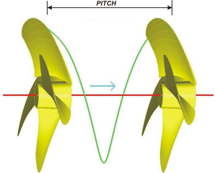
Pitch: Is the displacement a propeller makes in a complete spin of 360° degrees. This means that if we have a propeller of 150” pitch it will advance 150 inches for every complete spin as long as this is made in a solid surface; in a liquid enviroment, the propeller will obviously slide with less displacement.
The pitch concept is not exclusive for propellers, other mechanical devices like screws also use it. For instance, a screw with 5 mm of pitch will advance 5 mm for every complete turn when hit by the screwdriver. In fact, the "screw propeller" concept is literally making reference to that the propeller works exactly like a screw.
It is very important that both, pitch and diameter, are properly calculated. If for any given HP the pitch is too big, the propeller becomes heavy and demands more power than the engine can reach and vice-versa, if the pitch is too small then we have a light propeller that wouldn't absorb the engine's full power.
So, what would be the appropriate pitch? Certain parameters need to be checked like power, rpms, gear reduction, size of vessel, vessel application (i.e. a trawler or a tugboat needs power while a yacht requires velocity).
How do you measure propeller pitch
The procedure underlined below will give an approximate method to measure the pitch of a propeller of a boat.
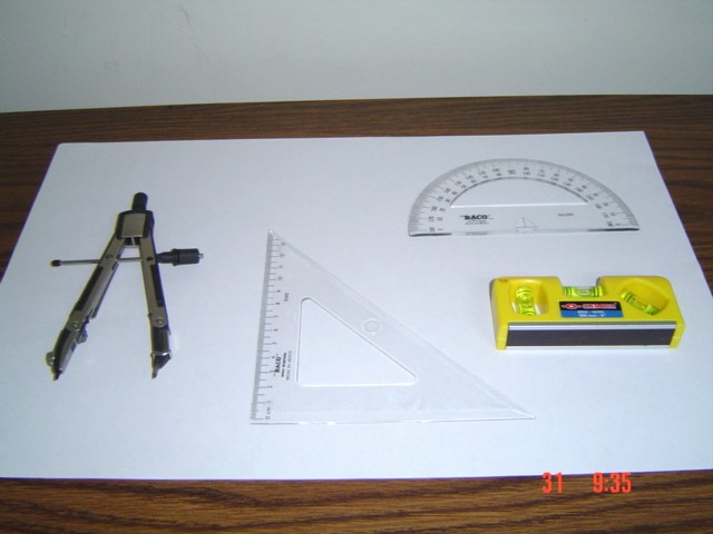
Necessary equipment to perform it:
Procedure : | |
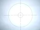
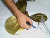
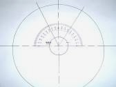
On a leveled surface, make a layout of: a center point, a circle with a diameter equal to the larger propeller hub diameter, and a circle with an approximate diameter that pass through the widest part of the blade to be measured. |
|
|

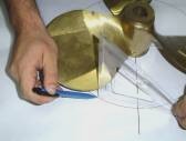
From the diameter that pass through the widest part of the blade, measure the perpendicular heights from the surface to the points located on both sides of the blade on the pitch side, that will serve to find the height differences between these two points. |
|
|
Finally, with the obtained data, the pitch will be determined with the following formula:
![]()
3 comments:
Top way to explain. Congratulations
I did not found the formula
Thanks for the article. Can u pls show us that formulae clearly?
Post a Comment