Monday, November 7, 2011

Submarine Escape Technology

With the loss of all hands aboard the S-4 in 1927 came an interest in the possibility of escaping from a sunken submarine. Lieutenant Swede Momsen together with several others designed an oblong, rubber bag that recycled exhaled air. It had a container or soda lime, which removed carbon dioxide from exhaust air and a charge of fresh air from the 225 pound system common to submarines of the time. The "lung" was strapped around the neck and chest and the escaping submariner breathed normally as he made a slow ascent up a line to a buoy on the surface.

Training on the device was wide-spread with hundred foot ascent towers in New London and Pearl Harbor. The short-coming of the device was its shallow depth limit. The Lung was good down to about one hundred feet, but a test depths of submarines at the time was over four hundred feet.

The Momsen Lung was designed as a vehicle for a one-way trip to the surface of the ocean. This singular quality would be replicated in subsequent devices through the next thirty years.

Momsen also pioneered the use of an escape bell which could be mated to the forward torpedo room hatch of a fleet type submarine. The bell was used in the rescue of submariners from the USS Squalus which had gone down from a main induction mishap off the coast of New Hampshire.

During the 1960's the British worked on a series of escape mechanisms. They simultaneously investigated compartment escapes and lock-out systems.

The former roughly equated to an escape from the after torpedo room of an American fleet type boat where a sleeve in the deck hatch was reversed and bolted in place. By partially flooding, then pressurizing the compartment with the 225 pound air system crew members could duck under the lip of the sleeve and get to the surface. The latter was equivalent to the escape trunk in the forward torpedo room of a fleet type boat where the same procedure could be replicated in successive four man escapes.

The British air lock system combined with a method of quick ascent called blow-and-go was successful down to depths of two hundred sixty feet. It should be noted that Germans had made many successful escapes using blow-and-go by riding a bubble or bubble mass to the surface. The British developed a Built-In-Breathing-System hood which was tested down to four hundred fifty feet in laboratory conditions. The rate of ascent was six feet per second with fifty second stops at five intervals.

Attempts to reproduce the laboratory ascents found that the system was good to only two hundred sixty feet, the same as the Blow-and-Go. The BIBS was improved to include an immersion suit which significantly increased the viability of free ascents down to about three hundred feet. They have concluded that ascents from depths below about three hundred fifty feet are too dangerous to attempt by marginally trained crew members.

During the 1960s the United States developed the Stienke Hood (Variously misspelled Steinke and Stenke). The free ascent device consisted of a plastic hood which, when partially charged with treated air, provided four hundred fifty one pounds of buoyancy. As the ascent progressed the crew member breathed the expanding air and excess air was discharged from the hood automatically. Once again the limit of this device was less than many test depths of submarines during the same period.

As test depths increased down to 2000 feet and as operational depths of modern nuclear powered boats out-distanced free ascent methodology the Navy adopted Submersible Emergency Inflation Suits or SEIS. These replicated the British technology and are currently carried aboard modern submarines. However, the gap between operational depths and recoverable depths meant that greater reliance had to be placed in a rescue vehicle that could dive to the stricken submarine, be attached to deck hatches and carry crew members to the surface. Successive dives can be made using this system and the depths at which rescues can be made equal that of the submarine's test depth.

The most significant problem facing the rescue vehicle approach is the tricky job of aligning the vehicle to the hull hatch. Angles-of-lie aggravate the problem and it is here that a new hard suit is of value. The Hardsuit 2000, an Atmospheric Diving System built by a Vancouver, Canada firm allows descents by divers down to 2000 feet. The system can be either umbilicaled to a surface ship or carried as a back pack for free descents. The ADS allows hoses for air, power and fluids to be run to a stricken submarine at hitherto impossible depths. Additionally, the ADS assists in the coupling of ROVS to deck hatches.

Not only does hardware continue to be developed for rescue of crew members at great depths, international submarine rescue seminars have become a bi-annual event with nearly every submarine possessing nation participating.

Submarine Hull Strength

The following excerpt is from the hull strength introductory chapter of "Steep Angles and Deep Dives". It provides some basic information on submarine hull strength including the definition of test depth and high yield:

Test depth is a theoretical number corresponding to the amount of area pressure that can be applied to a hull before it is violated by either distortion, warping, buckling or cracking. The pressure hull acts to prevent an equalization of pressure on both sides of the hull surface. When pressure is equal on both sides of a hull, such as is the case in a submarine's external ballast tanks, there is no need to attend to the problem of potential collapse.

Test depth can be thought of as an engineering estimate of what pressure will be required on one side of a hull to breach the hull, taking into account such factors of hull strength as hull diameter, hull thickness, framing, and intrusions. Naval engineers tend to be conservative in their estimates and the varied factors tend to render an estimate as just that, an estimate. The engineers back into the problem by first estimating the crush depth of a hull, then creating the theoretical test depth by a applying a decimal factor to the crush depth. Different national navies apply varying factors. The United States Navy has used a factor of 1.5, but this has changed many times. Of course, computers are able to make such estimates much more trust-worthy, however, the accounts described "Steep Angles and Deep Dives" are, for the most part, in hulls designed before the advent of the computer.

In the American Navy, hull designers depend on the experience of submarines to verify their estimates. Buships requires a submarine captain to immediately notify both Buships and the Chief of Naval Operations in writing when a boat under his command exceeds test depth. The captain's professional career may be jeopardized by a zealous attention to recording a dive that went wrong. Only in wartime can a captain reasonably explain the need to exceed test depth. For this reason submarines exceeding test depth sometimes fail to make note of the dive in their deck logs.

The simplest application of determining hull strength is the hull thickness. The thicker the hull metal the stronger the hull and the deeper the test depth, assuming all other factors are constant. Prior to the Balao class U.S. submarine, hulls were built of mild steel (MS) which had a maximum tensile strength of 60,000 pounds per square inch and a yield strength of 45,000 psi with 23 percent elongation. The thickness of hull plating until about 1943 was specified in terms of the weight of a square foot of plate rather than the actual thickness, and this was gradually increased from 20 pound plate (approximately one half inch) to twenty seven and a half pounds per square inch in the Salmon (SS-182).

Another change in the Balao class was the change in material used for hulls. High tensile steel was a chromium-vanadium alloy with a maximum tensile strength of 50,000 psi with 20 percent elongation. When the composition was changed to titanium-manganese alloy, because of wartime shortages, the strength dropped to 45,000 psi. The Salmon's hull was about seven eighths of an inch thick giving her a test depth of 250 feet. Conning tower shells were thicker as protection against surface guns.

The thick-skinned boats came along in 1942 with a test depth of 412 feet. These boats had the same seven eighths inch thick hull as Salmon, but the quality of hull steel ie., high tensile strength steel had significantly improved. The crush depth of these boats was estimated to be around 450 feet. Fleet type submarines built during the Second World War were to last through much of the cold war. These boats have careers that have lasted over fifty years with many still being used by foreign navies.

After the war the Navy built several fast attack submarines. These had hulls about an inch and a half thick. They had a test depth of 700 feet. The same hull thickness and quality of steel was used on the early nuclear submarines.

A modern nuclear powered submarine normally has a test depth of over 2000 feet. This huge increase in operational depth came about from increasing the thickness of a hull, from strides in improving the quality of steel, from improvements in the manufacturing process and in hull framing.

Steel is an alloy made up of several metals other than iron. These may include chromium, nickel, manganese, titanium and a host of others. Metallurgy is the science of combining these elements to produce an iron metal that meets a specific need, in this case a hull which is resistant to sea pressure. During the Second World War Krupp of Germany and others used advanced techniques to produce hull plating of unusually high quality. America inherited some of the formulae and steel mills benefited by the German experience.

The key to producing metal hulls suitable to deep diving submarines is the quality of yield strength in combination with compression strength. Accurately controlled element content and relatively high percentages of alloy additives produces strength. The compression strength curve is relatively flat until it reaches a point where the molecules can no longer bind, then the metal fails by cracking and splitting. On the other hand it is possible to produce a metal hull that has the quality of bending rather than rupturing. It yields under pressure where its elasticity, (elongation) gradually succumbs to increasing pressure. The trick for the metallurgist is to strike a compromise and to use the correct ratio of alloy elements to gain a hull plate that resists pressure to the maximum through high compression strength, but yields enough to forestall the rupturing of the metal.

Steel strength is often measured by tensile strength. In this test the metal is pulled on both ends until it parts. Tensile strength is related to compression strength even though the tests are opposite, one pulling and the other pushing. For this reason submarine steel strength is often measured in tensile strength, not withstanding the nature of sea pressure as a compression force.

American submarines such as the Seawolf and Virginia use HY (high yield) 100 metals. These designators attend to the elements used in the submarine hull's alloy where essentially the higher the number the more resilient and resistant the metal is to pressure.

The combination of elements to produce an alloy with great strength is only half the story of producing submarine hulls. The second factor in the manufacturing process is the tempering of the steel and shaping of the plates into a final form. Once again, the basic concept is that a slow-cooling steel tends to be resilient and a quick cooling steel tends to be brittle. Metallurgists in the middle ages learned this early on and after shaping a red hot sword on an anvil plunged it into water. This gave the sword a fine cutting edge resistant to chipping and dulling. The down side was that when struck by another sword it tended to shatter rather than yield. Thus, a submarine's hull plating is cooled at a specific rate designed to produce the best combination of stress and yield factors.

The shaping of the plate in the factory is accomplished with huge hydraulic rollers. The shaping process is also a compromise. Some alloys are cold rolled. This is the optimum in terms of preserving the alloy's strength in the shaping process, however, as the thickness of the plate increases the effect of the rolling becomes less and less. The modern mill now uses computers to cold roll submarine hull plates. Each pass through the rollers bends the steel a small amount until after many ( in some cases hundreds) of such passes through the rollers the plate conforms to the correct hull curvature.

In determining the diameter of the pressure hull the engineer takes into account the metal thickness that will be required to meet a given strength level. The less the diameter the thinner the metal can be. The size of machinery largely determines the diameters of submarines. As the design of the submarine progresses the diameter of the hull inevitably increases. (Modern Trident missile submarines have a forty three foot diameter pressure hull) This necessitates a thicker hull where the alloys used and the shaping process are constant. Once again, the hull design process is one of compromise where interplaying factors are balanced against one another until a final design with an estimate of test depth is reached.

The curved plates of metal to make up the submarine's hull are further strengthened by frames. Lateral framing was known to the Vikings, although they started with a hull shape and only after the strakes had been laid did they imbed the frames into the preformed hull. Submarine hull strength is in large part a function of frame strength and spacing. Cross sections of frames are normally "T" shaped and can be within the pressure hull, on the exterior of the pressure hull, or both. The externally braced hull was the standard in submarine design, because piping and conduit cannot penetrate frames without compromising strength. With modern welding techniques it has been possible to grip the hull plate to the frame with such force that external framing is successful.

The distance between frames is crucial to determining test depth since this distance is where a compressed hull will yield or fail. The distance is a design function taking into account the factors described in this section.

The cylinder is the optimal shape for a submarine hull. A sphere is better still, however, the shape of a sphere does not accommodate a moving vessel through water. Only in experimental and exploration vehicles is the spherical hull shape used. A submarine is in essence, a long cylinder, made up of many sections welded together.

The tapered ends of the fleet type submarine (forward torpedo room and after torpedo room) called for innovation since the cylindrical form had to be compromised. These compartments were flattened for hydrodynamic reasons. Fleet type boats had exterior framing, however, in these end compartments the frames were interior as well as exterior. The deviation from circularity although small, produced a bending moment putting the shell plating under compression and the face plate of the frame under tension. Thus, the mass-produced fleet type boats had framing partly on the inside and partly on the outside of the pressure hull.

Three dimensional curvature for modern hemispherical bows require conical shaping, and tapered hull plating that in turn requires extensive welding.

The welding of the many plates and commensurate framing necessitates the greatest care. The weld seam must have the same strength as the abutting hull plates. This means that if welding is accomplished by hand the welder must be of the highest technical competence. Although a submarine may be similar to others in its class each is essentially hand built. Automation is limited, but computerization is extensive.

Hull butting is exact. Each cylindrical hull section must precisely match the adjoining section. Each cylindrical section has its edges ground to an approximate forty five degree knife edge. When two sections are mated the two edges form a trough. Actually, there are two troughs, one on the inside of the cylinder and the other on the outside. The welder (or machine) places the first bead at the deepest point of the trough. The next weld layer is placed on top of the deeper layer. As the process continues and the wedge shaped trough widens, more and more beads are placed side by side to fill the trough. Many hundreds of beads are required to bring the level of beading to the surface of the abutting hull sections. It is a long and tedious job and quality inspections are constant.

Unfortunately, a perfect cylindrical hull with precise welding and engineered frame spacing must be punctured to allow various pipes, coaxial cables and rotating shafts access to the exterior of the hull. Wherever such a hull opening occurs the hull must be reinforced by building up the thickness of the surrounding area. The larger the opening (such as for hatches) the stronger must be the build-up. Even when every effort is made to compensate for the loss of strength from a hull opening the point of violation will be the point of failure when the hull exceeds test depth.

Time destroys the hull from several directions. The metal itself fatigues over time. Additionally, the sea takes its toll with corrosion eating at the metal. Hull modifications requiring welding, heat the hull and thereby reduce the effectiveness of the initial tempering. Nicks, gouges and scrapes collectively take their toll.

The Fleet Type boat designed and built during the Second World War were subsequently equipped with snorkels and modified into Guppies. These were often given to other nations under various alliances. Many of these boats are still operating as naval units in foreign navies. They are only now being replaced by more recently built boats.

Sunday, October 16, 2011

Marine Engineering Courses in India - MARINE ENGINEERING & RESEARCH INSTITUTE (MERI) - KOLKATA

MARINE ENGINEERING & RESEARCH INSTITUTE (Marine Engineering & Research Institute) Marine Engineering & Research Institute erstwhile Directorate of Marine Engineering Training (DMET), with its Headquarters at Kolkata and branch at Mumbai was established in the year 1949 to impart training to the Marine Engineering Cadets. The headquarters of the Institute is headed by the Director and the branch by the Dy. Director. The Marine Engineering & Research Institute Kolkata conducts 4 year Marine Engineering Course equivalent to Degree course in Marine Engineering. The intake capacity of the above course is 120 per year. Both institutes are fully equipped to impart effective training in all the branches of Marine Engineering. The cadets for admission to Marine Engineering & Research Institute, Kolkata, are selected through a combined all India entrance examination conducted by IITS, all over the country


The Marine Engineering Training in India had its formal beginning in 1927 on board the Training Ship 'T.S. Dufferin" which provided facilities for training both of nautical and engineering merchant navy personnel. The main consideration, when this Training Ship was inaugurated, was mainly to inculcate sea-sense in cadets.

With the country obtaining Independence in 1947, it was realized that the newly independent vast country was in need of a large Merchant Navy. At the same time vast technological changes brought in by the gigantic war efforts of the developed countries during World War II, also showed inadequacy of the training systems. As a result, on the recommendation of

Merchant Navy Officers Training Committee', constituted in 1947, by Govt. of India, immediately after independence, the function of pre-sea training of Marine Engineers was transferred to 'Directorate of Marine Engineering Training' from the year 1949 with its headquarters in Kolkata and a branch at Mumbai.

Marine Engg. Training at MERI, Kolkata has undergone several changes in 70 - decade.
In 1977 / 78, an expert committee nominated by Govt. of India, headed by Prof. Shankarlal recommended certain reorientation in

  • Course curriculum

  • Class contact hours

  • Practical Training / Pattern.

(MHRD accorded approval to graduation certificate issued by the Institution as equivalent to First degree in Marine Engg. with effect from 1982-entry for the purpose of recruitment to the Senior posts and services under Central Govt.)

(The Graduation certificate issued by the Institution also got recognition of The Institution of Engineers (India) as an exempting qualification from their A & B examinations from 1982 onwards.
*Further the course has also got the approval of AICTE.

*In order to meet the IMO requirements for Marine Engineers working on board the ship the training curriculum in this Institute has also been oriented to cover the STCW 95 convention.

*For Quality accreditation the 'System Manual' and the 'Procedure Manual' have already been prepared and the Institute is in the process of getting ISO-9000 certification.

marine engineering and reserch institute
INFRASTRUCTURE :
LAND AREA
33 acres (approx.) at P-19, Taratala Road, Kolkata 700 088.

CLASS ROOMS
4 Nos. which can accommodate 120 cadets & 10 Nos. which can accommodate 40 cadets.

LABORATORY
State of the art laboratories _ Mechanical Lab., Hydraulic Lab., Heat Lab., Electronic Lab., Electrical Lab., Control Lab., Boiler Lab., Computer Lab., Marpol Lab., Fire Fighting Lab., Simulation Lab., Seamanship Lab.

LIBRARY
Facility of full fledged technical library comparable to the very best in the country is available to the candidates in the training center and services available in terms of books, journals, videos and periodicals etc.

WORKSHOP
Fully equipped in-house workshop having Test Rig and working models of ship's machinery and component parts.

HOSTEL
Residence in the hostel is compulsory. Final year cadets are given single seated rooms while junior cadets share accommodation in the hostels. All cadets are required to be members of the joint mess run by the cadets which is subsidised by Grant-in-Aid from the Govt. A cooperative store is run by the cadets for their benefits. All cadets are required to be members of the cooperative store.

UNIFORM
Cadets must wear uniform throughout their period of training. At the commencement of training, articles of uniform as per printed "list of uniform" of this Directorate are to be purchased by the cadet.

DISCIPLINE
High standard of paramilitary type of discipline is maintained in this Institution. All cadets must carefully read and understand the standing orders, rules and regulations etc. and abide by them at all times. The Director reserves the right to impose on a cadet punishment including fine, suspension and dismissal from the training in the event of any breach of discipline.

SCHOLARSHIP
A number of scholarships both on merit and financial conditions of the parents are available to the cadets of MERI.

DEPOSIT
Personal accounts are opened in the name of each cadet at the time of joining the course and are operated throughout his period of training of four years. Yearly statements will be
given to the cadets.

FEES & OTHER EXPENSES
FOR INDIAN CADETS :
Quarterly hostel rent, tuition fees, mess estt. charges etc.
(@Rs. 700/- per month for general cadets and @Rs. 600/- per month
for SC/ST cadets ).

For General cadets - Rs. 2100/- (quarterly).

For SC/ST cadets - Rs. 1800/- (quarterly).
Mess charges (Rs. 1000/- p.m.) for all cadets Rs. 3000/- (quarterly).
Caution money ( one time ) for all cadets Rs. 500/-
Medical & Sports charge ( Rs. 100/- per month) for all cadets
Rs. 300/- (quarterly).
Computer / Internet System charges (Rs. 150/- p.m.) for all cadets
Rs. 450/- (quarterly).
Upkeepment of hostel / hygiene (Rs. 30/- p.m.) for all cadets
Rs. 90/- (quarterly).

FOR FOREIGN CADETS :
Mess estt. and tuition fees etc. U.S. $4000 per annum.
Medical, Sports Charge, Caution U.S. $300 per annum.
money etc.
Mess charges (variable) Same as applicable to Indian cadets.

ENTRY STANDARDS
1. The maximum at entry level :
(I) For general category candidates not to exceed 20 years.
(II) For SC/ST category candidates not to exceed 25 years.

2.The educational standards for entry to this course is a pass in 10+2 school level with Physics, Chemistry and Mathematics and qualify through Joint Entrance Examination conducted by Indian Institute of Technology all over India followed by counseling.

3.Qualified candidates are required to produce a detailed medical report of self from a qualified body during counseling. An appropriate medical board also checks the eye sight in particular and all other aspects in general at the same time. Only successful candidates through both these tests are eligible for admission.

DURATION OF COURSE :

The training curriculum is conducted in eight semesters spread over four years and makes adequate coverage as per International Marine Organizations requirements / regulations.

The course also includes in-depth coverage of various allied engineering topics e.g. Mechanics of Machines, Mechanics of Materials, Advanced Mathematics, Advanced Computer Science, Electronics, Fluid Mechanics etc. so that a passed candidate has adequate reserve to pursue the development and research work in his chosen area, if he so desires.

Extensive further training is given in Physical Exercise, Parade, Housekeeping, Swimming and Outdoor games, under daily routine in order to ensure that every trainee acquires the mental, moral and physical attributes essential for development as Marine Engineer. Every trainee will be issued a Training and Assessment Record Book (TAR) and he is responsible for upkeep and security of the book.

On successful completion of this training program, assessment and examination by the administration, trainees should be competent to carry out safely the watch keeping duties of an engineer officer on board a ship and be fully conversant with the maintenance and operation of machinery and equipment fitted on board a ship.

Campus interview is held every year by different Shipping Companies and all the cadets are absorbed in different Indian and foreign shipping companies. Successful Marine Engineers from this Institute have been manning the ships holding the life line of economy not only of India, but also of many foreign countries.

Contact Person

Shri S.Mukhopadhya, Director
Marine Engineering and Research Institute,
P-19, New Taratalla Road,
Kolkatta - 700 088
Tel No: 033-4014794/76
Fax No:033-4014333
E-Mail:director@merical.ac.in

Web Site : www.merical.ac.in

INDIAN SHIPPING INDUSTRY - SOME FACTS

Shipping plays an important role in the transport sector of India's economy. Approximately, 90 per cent of the country's trade by volume (70 per cent in terms of value) is moved by sea. India has the largest merchant shipping fleet among the developing countries and ranks 20th amongest the countries with the largest cargo carrying fleet with 8.83 million GT as on 01.06.2008 and the average of the fleet being 18 years. Indian maritime sector facilities not only transportation of national and international cargo but also provides a variety of other services such as cargo handling services, shipbuilding and ship repairing, freight forwarding, lighthouse facilities and training of marine personnel, etc.
Coastal Shipping
Coastal Shipping is an energy-efficient, environment-friendly and economical mode of transport in the Indian transport network and a crucial component for the development of domestic industry and trade. India, with her 7,517 km long costline studded with 13 major ports and 200 non-major ports provides congenial and favourable conditions for the development of this alternate mode of transport.
Aids to Navigation
Since Independence, India has made rapied growth in aids to Marine Navigation. From 17 Lighthouses prior to Independence, the present strength of aids to Navigation consists of 171 Lighthouses, one Lightship, one Loran-C Chain Stations, 59 Racons, 21 Deep Sea Lighted Buoys 01 wreck making and 22 installations under Differential Global Positioning System (DGPS). To cater the needs of light stations in the islands and for maintaining the buoys, the Directorate General of Lighthouses and Lighships is maintaining three launches, one mechanised boad and two large ocean going vessels, M.V. Sagardeep-II ad M.V. Pardeep.
Maritime Training
The Director General of Shipping is responsible for creation of the trained manpower required for the merchant navy fleet of the country. This national obligation is being met through the Government training institutes and a number of other approved training institutes in the private sector. The importance of organised training was recognised in the year 1927 when the Training Ship "Dufferin" was established. Since then many highly skilled Indian seafarers have been trained in India who have earned commendable reputation at home and abroad.

The four training institutes, which were established by the Government are:-
  1. Trainingn Ship 'Chanakya' which conducts
    1. Three years B.Sc degree course in Nautical Sciences under the University of Mumbai
    2. Pre-Sea training course for Deck Cadets.
  2. Marine Engineering and Research Institute (MERI), Kolkata which conducts four years degree course in Marine Engineering under Jadavpur University.
  3. Marine Engineering & Research Institute (MERI), Mumbai conduct
    1. one year Training Marine Engineering Course for graduate Mechnical Engineerings and
    2. Three-year B.Sc. degree course in Martime Sciences (polyvalent degree) under the University of Mumbai
  4. LBS College of Advance Maritime Studies & Research, Mumbai, conducts alomst 46 post-sea training courses for serving Marine Officers.
In addition to the above, there are about 124 training institutes in the private sector approved by the Director General of Shipping, imparting pre-sea and post-sea training in various disciplines.
Shipping Corporation of India Limited

Shipping Corporatoin of India Ltd Logo The Shipping Corporation of India Ltd (SCI) was formed on 2nd October 1961. The present authorised capital of the Company is Rs. 450 crore and paid up capital is Rs 282.30 crore. The status of SCI has been changed from a private limited company to Public limited from 18 September 1992. The SCI was conferred 'Mini Ratna' status by the Government of India on 24 Feburary 2000. At present, the Government is holding 80.12 per cent of share capital and the balance is held by financial institutions, public and others (NRIs, Corporate Bodies, etc.). SCI signed Memorandum of Understanding with the Ministry of Shipping, Road Transport & Highways, Government of India on 27 March 2008.

On 8th March, 2007, SCI was awarded MOU Excellence Certificate for the year 2004-05 and 2005-06 by the Government of India, Ministry of Heavy Industry and Public Enterprises, Department of Public Enterprises. SCI was the winner of the best international solution award and the third annual HBSC global payments and cash management partnership award, which was posted in Bangaluru on 5th November 2007. The SCI won the "Shipowner/operator of the year 2007" at the seatrade middle east and Indian sub-continental award 2007, held in Dubai in November, 2007 SCI also won the "Shipowner of the year 2007" at Lloyds list Middle east and Indian Sub-continental award, held in Mumbai in November 2007

Cochin Shipyard Limited

Cochin Shipyard Limited Logo Situated in the Western coast of India in the city Cochin, State of Kerla, Cochin Shipyard is the largest shipyard in the country. Incorporated in the year 1972, Cochin Shipyard can build ships upto 1,10,000 DWT and repair ships upto 1,25,000 DWT. The year has built varied types of ships including tankers, bulk carriers, ports crafts, offshore vessels and passenger vessels. The orders executed by CSL in recent past include carriers for M/s Clipper Group, Bahamas, firefighting tugs for M/s ATCO, Saudi Arabia and Platform Supply Vessels for M/s Deep Sea Supplies, Norway.
The yard is also a leading ship-repairer of the country and has repaired more than 1200 ships of all types. These include upgradation of vessels belonging to ONGC, periodical lay up repairs and life extension of ships of Navy and Coast Guard. The yard had been consistently achieving profits for the last several years.

Garden Reach Shipbuilders & Engineers LTD. KOLKATA

Garden Reach Shipbuilders & Engineers Ltd The Garden Reach Shipbuilders & Engineers Limited was incorporated as a joint stock company in 1934, under the name M/s Garden Reach Worskhop Limited (GRW). The Government of India acquired the company in 1960. It was renamed as "Garden Reach Shipbuilders & Engineers Limited (GRSE)" on 01 January 1977.
The company builds and repairs warships and auxillary vessels for the Navy and Cost Guard. Its present product range includes corvettes, frigates, fleet tankers, patrol-vessels, fast attack craft, high technology ship brone equipment, portable bailey type steel bridges, turbine pumps for the agricultural sector, Marine Sewage Treatment Plants, Diesel Engines etc. "Mini-Ratna Status Category-I" was conferred on GRSE on 5 September 2006.

Hindustan Shipyard Limited, VISAKHAPATNAM

Hindustan Shipyard Limited Hindustan Shipyard Limited (HSL), Visakhapatnam as set up in 1941 in the private sector and was taken over by the Government in 1952. In 1962, the shipyard became a central public sector enterprise. The shipbuilding capacity of the yard is 3.5 pioneer class vessels of 21,500 DWT each. The maximum size of vessel that could be built is 50,000 DWT.
HSL is the first shipbuilding yard in the country which was awarded ISO:9001 certification by Lloyds Register of Quality Assurance, London for international standard of quality assurance. For ship repairs, the yard has facilities such as modern dry dock, wet basin, repair shops, etc., and it can undertake repairs of submarine, tankers adn ships up to 70,000 DWT. HSL has an exclusive offshore platform construction yard capable of constructing two platforms per annum.

Hooghly Dock and Port Engineers Limited, KOLKATA

Hooghly Dock and Port Engineers Ltd Hooghly Dock and Port Engineers Limited (HDPEL), Kolkata became a Central Publi Sector Undertaking in 1984. The company has two working units in Howrah District of West Bengal, one at Salkia and another at Nazirgunge. The installed capacity in shipbuilding is 1,100 tonnes per annum and in ship repairs 125 ships per annum. Apart from a dry dock and a jetty, it has six shipways. The yard is capable of constructing various types of ships (including passenger ships) and other vessels such as dredgers, tugs, floating dry docks, fishing trawlers, supply-cum-support vessels, multi-purpose harbour vessels, lighhouse tender vessels, barges, mooring launches, etc., and undertaking repairs of different types of vessels.
Marine Propellers- Pitch and How to Measure it?

A propeller can be defined as follows: A mechanical device formed by two or more blades that spin around a shaft and produces a propelling force in ships/boats.

There are various technical terms to define the propeller's characteristics such as: diameter, pitch, disc area relation, hub, bore etc. All these characteristics are calculated to design the optimal propeller accordingly to specific needs of the ship owner and ship characteristics.

In this blog entry, we are going to define what is the propeller pitch and the importance at the time to select it.

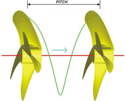
Pitch: Is the displacement a propeller makes in a complete spin of 360° degrees. This means that if we have a propeller of 150” pitch it will advance 150 inches for every complete spin as long as this is made in a solid surface; in a liquid enviroment, the propeller will obviously slide with less displacement.

The pitch concept is not exclusive for propellers, other mechanical devices like screws also use it. For instance, a screw with 5 mm of pitch will advance 5 mm for every complete turn when hit by the screwdriver. In fact, the "screw propeller" concept is literally making reference to that the propeller works exactly like a screw.

It is very important that both, pitch and diameter, are properly calculated. If for any given HP the pitch is too big, the propeller becomes heavy and demands more power than the engine can reach and vice-versa, if the pitch is too small then we have a light propeller that wouldn't absorb the engine's full power.

So, what would be the appropriate pitch? Certain parameters need to be checked like power, rpms, gear reduction, size of vessel, vessel application (i.e. a trawler or a tugboat needs power while a yacht requires velocity).

How do you measure propeller pitch

The procedure underlined below will give an approximate method to measure the pitch of a propeller of a boat.

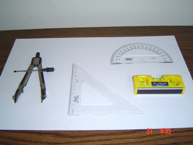
Necessary equipment to perform it:

  • Protractor (angle measurement)
  • Level
  • Plumb Line (not necessary on small props)
  • Square Set or Squadron (mm, in or ft)
  • Compass

Procedure :


Equipment

On a leveled surface, make a layout of: a center point, a circle with a diameter equal to the larger propeller hub diameter, and a circle with an approximate diameter that pass through the widest part of the blade to be measured.

Put the propeller with the pitch side up, and center it with the larger diameter previously layout.


Leveled surface


Necessary Layouts

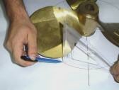
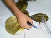
From the diameter that pass through the widest part of the blade, measure the perpendicular heights from the surface to the points located on both sides of the blade on the pitch side, that will serve to find the height differences between these two points.

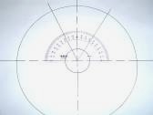
In this procedure, layout on the surface and over the layout diameter , the two points that will help us to define the projected angle over the surface, which will be measured with the protractor as shown in the picture.


Measuning heights from the layout diameter,
and marking the proyected points


Measured Angle

Finally, with the obtained data, the pitch will be determined with the following formula:

Marine Propellers- Optimum Number of Blades

The choice of the number of blades is one of the first decisions to be made in the design of a screw propeller.

Marine screw propellers usually have 3, 4 or 5 blades, of which four blades are the most common.

Two-bladed propellers are used on sailing ships with auxiliary power, as they offer the lower resistance when in the sailing condition.

The problem with two-bladed propellers for most vessels is that such propellers require very large diameters to get the blade area required for effective thrust.

Three-bladed propellers have generally proven to be the best compromise between blade area and efficiency.

Four or five-bladed propellers and even more blades are useful for two reasons. First, their extra blades create more total blade area with the same or less diameter. 4 blades propellers, however, would seldom be as efficient as the three-bladed because the closer blades create additional turbulence, literally scrambling up each other's water flow.

Another reason to use more than three blades is to reduce vibration. If a propeller is in the habit of producing annoying, rhythmic thumping and humming, a propeller with more blades will often solve the problem. Every time the blades of the propeller pass under the hull or by the strut, they cause a change in pressure that causes a push. If the push is strong enough, it generates a bang. Lots of rapid bangs equal vibration.

Conclusion: the less number of blades the more efficiency, the higher number of blades the smoothest and uniform performance. This must be always taken in consideration when selecting the proper Diameter, Pitch, Blade Area and Shape.

Marine Propellers- Manufacturing Tolerances

In the area of the propulsion many applications exist, that they go from crafts of fishing, of pleasure, of load and of speed between many other's.

It's for that reason that a classification of propeller's exists that determine the tolerances that it should have a propeller, according to the necessities of a craft.

The ISO 484/ 2-1981 Norm establishes the tolerances for the production of propeller's in all their geometric dimension. And divide them in the following classes

This norm contemplates all the dimensions of the propeller's like they are: Pitch, Diameter, Chord Length, Rake, Thickness and separation between blades

The norm requests that they are revised the dimensions of certain radios, this according to the type of propeller that is manufactured.

Class

Ratio

S & I

Close to the hub 0.4, 0.5, 0.6, 0.7, 0.8, 0.9, 0.95

II

Close to the hub 0.5, 0.7, 0.9

III

Close to the hub 0.5, 0.7, 0.9

The tolerances in pitch vary between the several classes how it show the following chart.

PITCH

S

I

II

III

Local pitch

± 1.5%

± 2%

± 3%

---

Prom. pitch for ratio

± 1%

± 1.5%

± 2%

± 5%

Prom. pitch for blade

± 0.75%

± 1%

± 1.5%

± 4%

Prom. pitch for propeller

± 0.5%

± 0.75%

± 1%

± 3%

The tolerances for the angular deviation between two serial blades are given according to the following chart.

Class

Angular Tol.

S y I

± 1º

II y III

± 2º

TOLERANCES ON TICKNESS

Clase

S

I

II

III

Max. Tol. with a minimum of

+2%

2mm

+ 2.5%

2.5mm

+4%

4mm

+6%

6mm

Min. Tol. with a minimum of

-1%

-1mm

-1.5%

-1.5mm

-2%

-2mm

-4%

-4mm

TOLERANCES ON RAKE

Class

S

I

II

III

Tolerance

± 0.5%

± 1%

± 1.5%

± 3%

NOTE: Rake is expressed like a percentage of the diameter of the propeller.

TOLERANCES ON THE LENGTH OF THE BLADE SECTIONS

Class

S

I

II

III

Tolerance with a minimum of

± 1.5%

7mm

± 2%

10mm

± 3%

13mm

± 5%

15mm

TOLERANCES IN DIAMETER

Class

S

I

II

III

Tolerance

± 0.2%

± 0.3%

± 0.4%

±0.5%

All the previous tolerances define the geometry of a propeller in accordance with the ISO 484/ 2-1981 Norm.

The same as this norm for the geometry of the propeller exists, the norm is also used SAE-J755 like reference in order to scheme the hub of a propeller.

This contains specified the dimensions of the most common standard bores, the same as the dimensions of the keyway.

These tolerances are those that they are considered in the production of any RICE propeller.

Marine Propellers - What is the best material

Properties of Bronze for Marine Propellers

COMPARATIVE SERVICE DATA. The superiority of nickel aluminum bronze has been convincingly demonstrated by an in-service test.

One propeller of each material was installed on a 6,000 ton twin screw carrier, which subjects its wheels to unusually severe service by operating on the Orinoco River in Venezuela.

The sand bars and sand in suspension in this river are responsible for damage to the ship’s propellers, needing frequent reconditioning or replacement.

The nickel aluminum bronze (starboard) propeller has suffered little mechanical damage or erosion, while the manganese bronze (port) propeller was rather severely damaged and required frequent repair.

The U.S. Navy is using nickel aluminum bronze material for propellers for ice-breaking service, and after a full season of operation excellent results were noted.

Propeller efficiency. Less obvious perhaps than the data presented in Table 1, but more important from a service standpoint, is propeller efficiency. The design engineers are most impressed by the ability of nickel aluminum bronze to retain its original smooth machined surface over a long period of time, thereby retaining its high efficiency factor. Numerically the improvement in efficiency would lie in the order of 1.5-3.0 per cent, with resultant fuel savings. The exact efficiency increase would depend upon the propeller size, design factors and length of service.

Design Benefit. As nickel aluminum bronze is in itself approximately 10 per cent lighter in weight than manganese bronze, and can be designed to thinner sections because of its higher strength, other advantages become apparent. For example, loading stresses on the tailshaft and bearings are reduce, thus permitting smaller shafts.

Resistance to Notch Sensitivity. The ability of nickel aluminum bronze to resist failure under impact when notched, contributes greatly to its value as a propeller material.

Maintenance. Maintenance of nickel aluminum bronze propellers is greatly reduced compared to that of manganese bze it has superior resistance to bending, breaking and wearing, including cavitation are directly associated with the material properties.

Reparability. Nickel aluminum bronze is readily reparable with the inert gas process, or by direct electric rod welding. Little or no pre-heat is required, and unlike to copper-zinc brasses, it is not subject to stress corrosion cracking and therefore does not necessarily require a stress relief treatment.

Propeller cost. Reduced weight of nickel aluminum bronze in conjunction with increased strength of the material allows designing the propeller approximately 15 % less in weight than a comparable manganese bze propeller. Although the former is more costly by the price per pound, the long term cost reduction is appreciable.

TABLE 1 - TEST RESULTS OF NICKEL ALUMINUM AND MANGANESE BRONZE

Item

Nickel Aluminum Bronze

Manganese Bronze

Chemical composition %

Copper

78 - 81

55 – 60

Zinc

In “all others”

Reminder

Nickel

4.5 - 5.5

-

Iron

3.5 –5.5

0.9 – 2.0

Manganese

0.5 – 1.0

0.3 – 0.9

Aluminum

9.0 – 10.3

0.7 – 1.0

Lead

0.01 max

0.4 max

Tin

In “all others”

1.5 max

All Others

0.5 max

-

Mechanical Properties (Normal Range)

Yield

35 – 43,000 psi

27 – 33,000 psi

Tensile 80 - 95,000 psi 60 - 72,000 psi

% Elong in 2 in

15 – 30

20 – 35

Proof stress

28,000 psi

14 – 16,000 psi

Brinell hardness

152 – 190

112 – 130

Fatigue – air

21 – 25,000 psi

9 – 14,000 psi

Fatigue – salt water

18 – 22,000 psi

9 – 12,500 psi

Density – lb/cu in

0.273

0.297

Spin Test

Weight loss – grams

2.48

9.21

Loss – Mg/in2/day

Mg/dm2/day

6.5

99.0

24.0

376.0

In penetration/yr

0.019

0.063

At tip – in

0.005

0.012


Propellers of nickel aluminum bronze

Propellers of manganese bronze